

Control of line equipment
Immersion heaters, filtration units, dosing pumps, ventilation plant and the rest of the line's equipment all run under the control system.
The control system visualises the production process and drives every stage of the process cycle automatically. The operator supervises and responds to deviations, rather than setting regimes by hand.
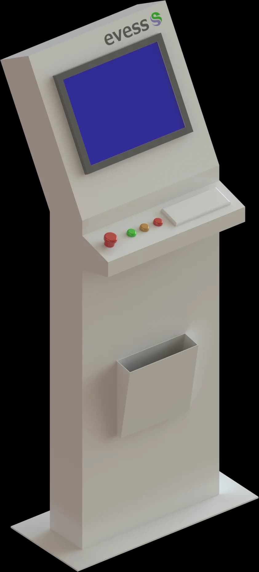
At the core sit a control panel housing an industrial PLC and an operator console with a touchscreen HMI. The controller polls the temperature, level and position sensors and drives heating, cooling, the rectifiers and the hoist drives.
Processor-controlled rectifiers integrate directly: programmable current and voltage regimes hold the process precisely and deliver an even coating thickness.
The control system architecture is developed as part of the full design documentation package, alongside the process flow diagrams, 3D layouts and equipment specifications.
Immersion heaters, filtration units, dosing pumps, ventilation plant and the rest of the line's equipment all run under the control system.
The system cycles jigs between tanks to a defined algorithm - immersion times and process sequence are held exactly, with no operator influence on either.
Processor-controlled rectifiers integrate into the control system directly: programmable current and voltage regimes are what give an even coating thickness.
Any number of process recipes can be defined for different part types and coatings - every operation is standardised by its recipe rather than by operator habit.
The system continuously checks the condition of line equipment, sensors and actuators, and raises alarm and warning messages and signals.
Logs of the recipes run, the part types processed and every alarm and warning raised - the history of each batch stays available for analysis.
The panel visualises the process and puts an intuitive menu in the operator's own language: equipment control, entry of recipe parameters, review of the internal logs and everything else needed to run the line.
Remote access over the internet is built in: on request the system reports current parameters for each part of the line, the internal logs and whatever else is needed.
Displayed on screen
The line mimic shows tank status and the parameters under control. This demonstration schematic is based on the interface from a delivered project.
jig route · hoists 1 and 2
Electrolyte temperature
20.4 °C
within setpoint
Current
412 A
within setpoint
Voltage
17.8 V
within setpoint
Immersion time
38:20
within setpoint
A demonstration of the EVESS interface. The values shown are illustrative and are not the parameters of a real process.
The control system is engineered as part of the complete line project.