

Aluminium anodizing lines
An anodizing line is a sequence of process tanks - degreasing, etching, desmutting, anodizing, colouring, sealing and cascade rinsing - linked by a transport system and supported by rectifiers, ventilation, chemical dosing and effluent treatment. EVESS engineers, manufactures and commissions those lines turnkey.
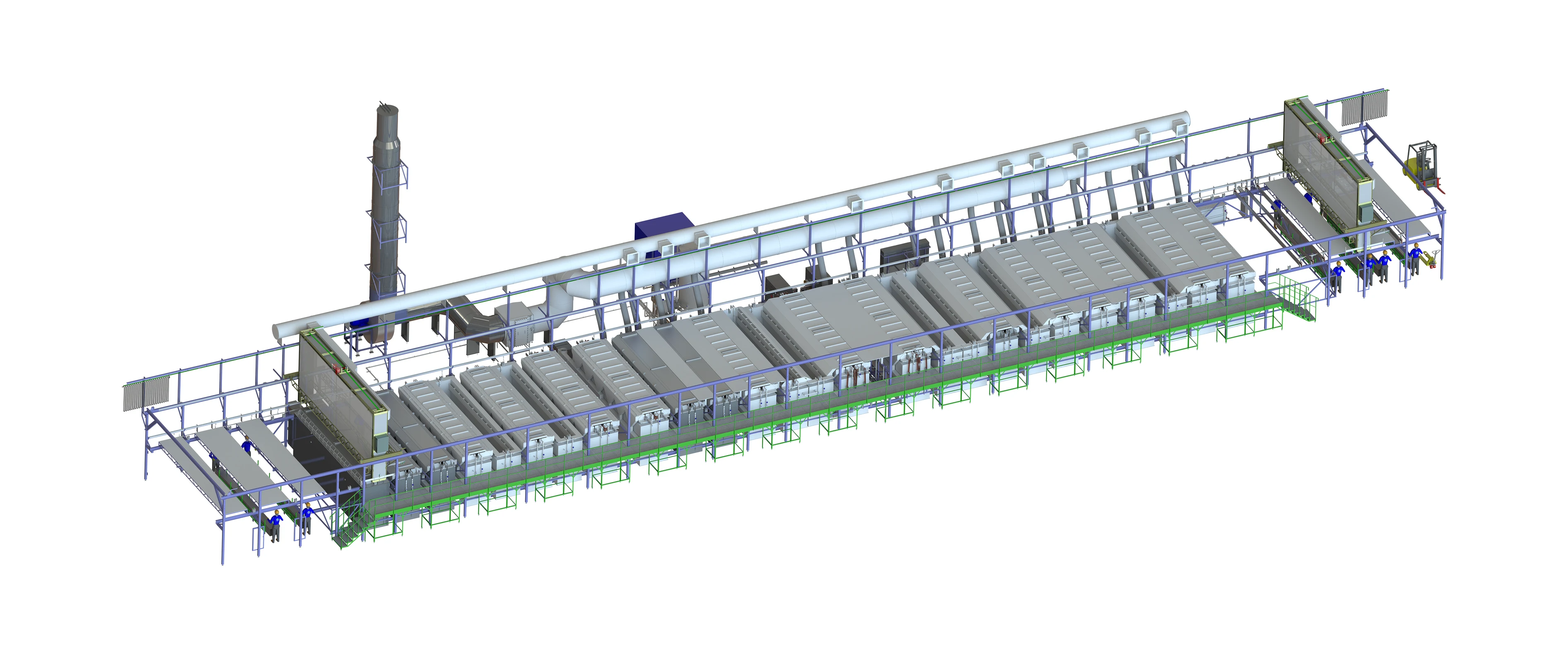
Levels of automation
| Throughput | Labour | Best suited to | |
|---|---|---|---|
| Manual | Low | 1–2 operators per shift | Small batches, development work |
| Semi-automatic | Medium | 1 operator per shift | Medium volumes, mixed part range |
| Automated | High | Supervision only | Series production |
What the line includes
Each component is covered in detail further down this page.
Line components and systems
Every component is designed and built as part of one line: transport, power, heat, air and effluent are calculated together rather than picked off a catalogue page.
Hoists
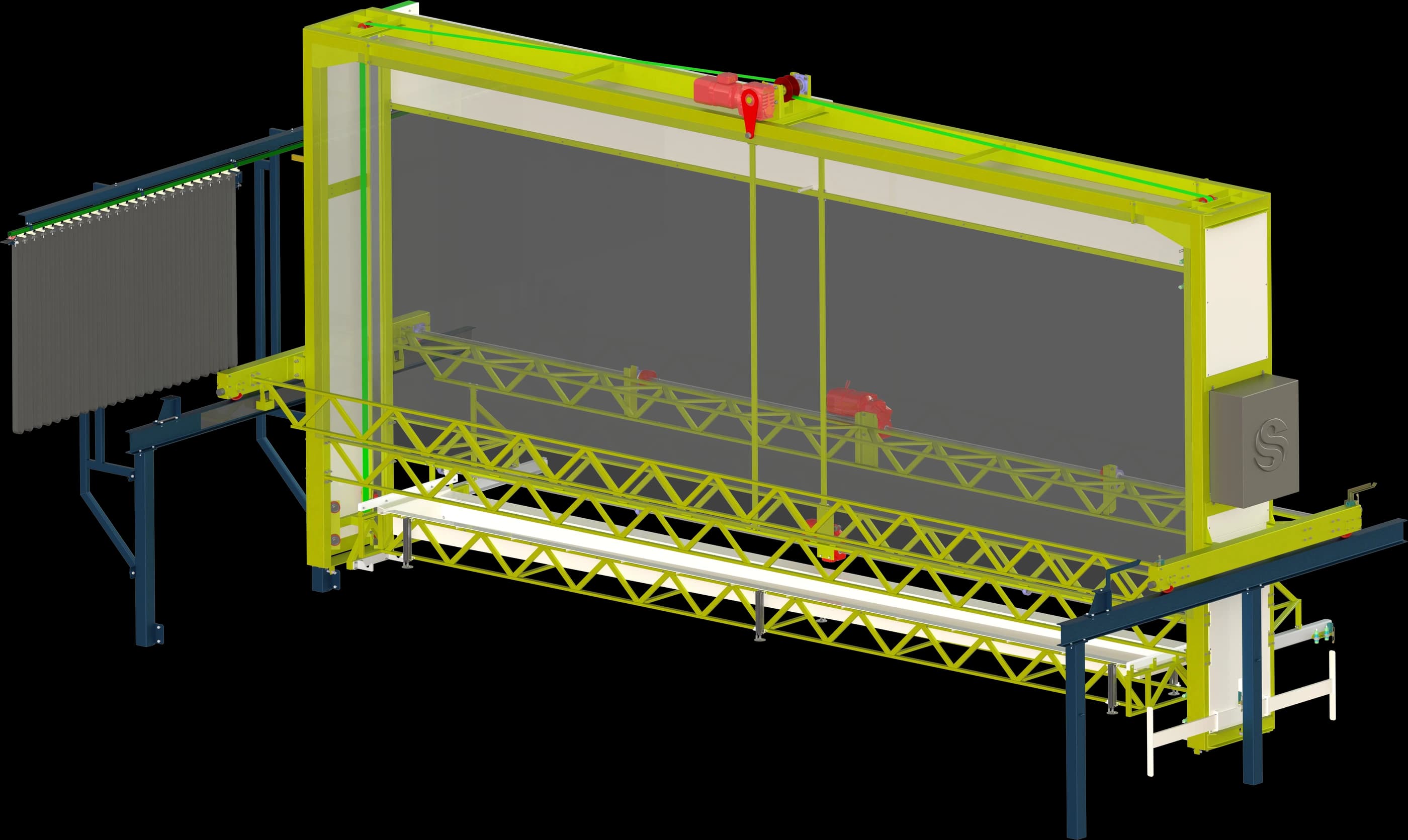
The hoist on a plating line is a programmable lifting and transport system. It cycles the tooling - jigs or barrels - between tanks to a defined algorithm, holding immersion times and process sequence exactly, with no operator influence on either.
What distinguishes the EVESS gantry hoist is its enclosure: a PVC-membrane skin on a frame that forms a sealed volume and stops mists and vapours escaping into the shop.
Forced extraction is ducted over every tank and connected to the enclosure, so a stable negative pressure is maintained inside and no vapour escapes into the workspace uncontrolled.
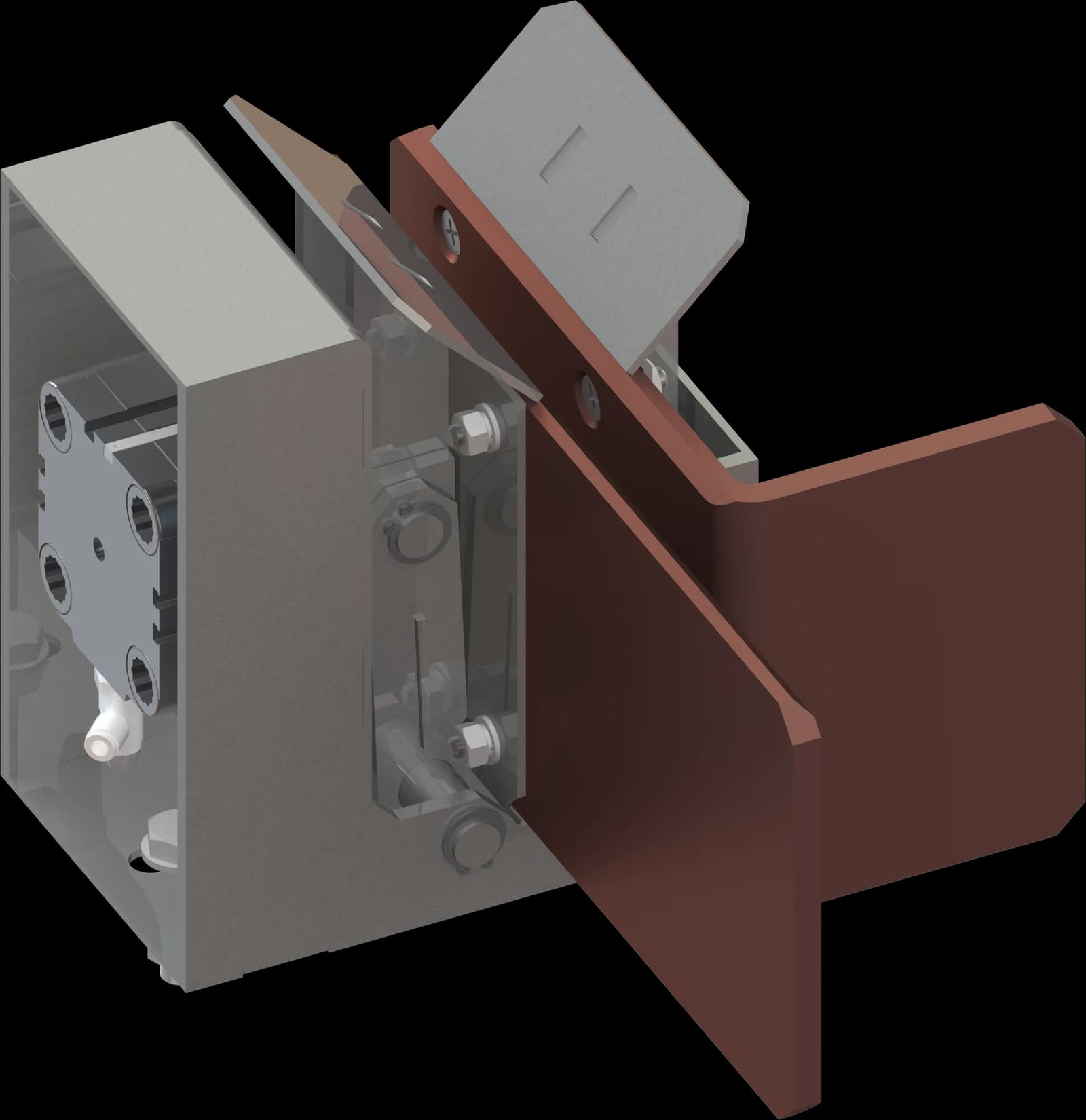
Contact seats
Contact seats position the loaded jigs precisely, hold them securely in the tank and - where required - carry current from the supply to the parts being processed.
Current-carrying seats are fitted with a copper bus-bar: beyond mechanical location, they give an electrical connection with no voltage drop even at high currents.
Versions by current rating
Up to 3,000 A
Mechanical or pneumatic contact seat construction.
Above 3,000 A
Pneumatic contact seat construction.
Combined heating unit
Most surface finishing processes run at a tightly specified electrolyte temperature. Drift lowers current efficiency, degrades the coating - roughness, peeling - shifts the electrolyte composition and drives up additive and energy consumption.
The combined heating system pairs two heat sources: a coil in the tank base fed by steam or hot water, and electric immersion heaters along the walls. Control comes from a panel with temperature sensors, solenoid and shut-off valves and a steam trap.
The control panel compares sensor readings against the setpoint and drives the actuators. In a fault condition - overheat, sensor failure, loss of flow - it closes the shut-off valve and de-energises the heaters.
Why combined heating
Fast to temperature
Steam holds the base temperature; the electric heaters speed recovery after cold parts are loaded, or at line start-up.
Even heating
The coil warms the full volume gently without local hot spots, while the heaters trim the temperature where it is needed.
Accurate holding
Electric heating integrates readily into the control system and holds the setpoint even when steam supply fluctuates.
Fault tolerance
Two independent circuits: if steam is interrupted, the electric circuit prevents both scrap and a line stoppage.
Cooling system
Cooling is one of the defining pieces of process equipment: the quality, thickness and protective properties of the coating depend directly on how stable and how effective it is.
Without heat removal the temperature in the working zone climbs uncontrolled and the process breaks down. Overheating produces a porous, uneven coating structure, while high temperature accelerates water evaporation and the breakdown of electrolyte components, shortening bath life.
The job of the cooling system is to hold the electrolyte within a narrow process window so results stay stable and repeatable. Structurally it is a closed circuit built for efficient heat exchange - an engineered system on which the thermal stability of the process, and therefore the quality of the finished product, directly depends.
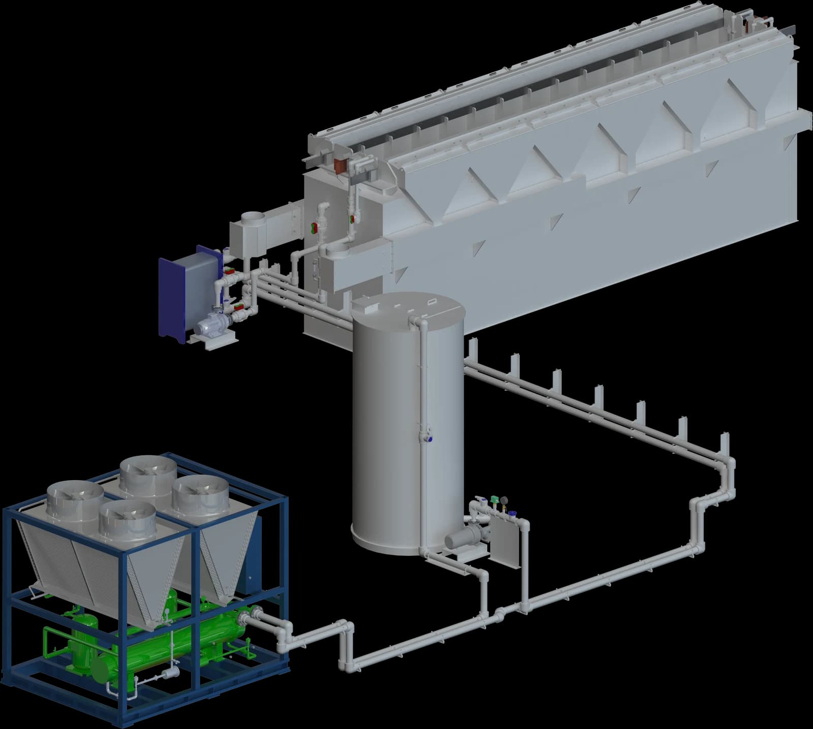
Components and operating principle
Heat exchange devices
The main path for heat to travel from hot electrolyte to coolant. Internal coils are the most common solution: made from chemically resistant corrosion-proof alloys, because they sit permanently in aggressive acid electrolyte - sulphuric, oxalic, chromic - and run along the tank walls or base, as close to the working zone as possible. The alternative is an external plate or shell-and-tube heat exchanger with the electrolyte circulated through it by a dedicated pump. That removes any contact between coolant and electrolyte and prevents bath contamination in the event of a leak, at the cost of a more complex system.
Coolant and circulation
The coolant is most often water - process or softened. Where tighter control is needed, or in unheated buildings, glycol solutions are used or the system is connected to a chiller. A pump circulates the coolant through the heat exchanger.
Control and instrumentation
An automated control loop: temperature sensors in the electrolyte volume - often at several points, to verify an even temperature field - a controller comparing actual temperature against the setpoint, and a three-way control valve on the cold water supply. The valve blends hot water leaving the exchanger with cold water from the main, holding temperature accurately without cycling the pump on and off, which significantly extends equipment life.
Pipework
Mains, isolation valves for maintenance, and filters that keep particulates out of the coolant before they can block the exchanger's channels.
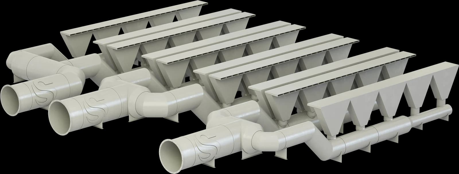
Lip extraction
Lip extraction is the core of local exhaust ventilation in a surface finishing shop: it captures vapours, gases and mists directly at the bath surface, before they can spread through the working area.
Because they sit in permanent contact with aggressive media, the hoods are made from chemically resistant polymers: polypropylene (PP) for most acid and alkaline duties, PVC up to +60 °C, and PVDF for particularly aggressive media and elevated temperatures.
Effective lip extraction protects the workforce, prevents corrosion of the building structure and the equipment, and is what keeps the plant compliant with occupational health and environmental requirements.
Exhaust ventilation and gas cleaning
The exhaust system removes aggressive vapours, gases and mists from the working area, carries the contaminated air through filtration or absorption equipment, and discharges cleaned air to atmosphere at a safe height.
Ductwork is built from chemically resistant materials; flanges and fasteners are corrosion-proof; seals are EPDM, Viton or PTFE depending on the media.
The corrosion-resistant fan is installed downstream of the filter or scrubber, on the clean-air side - which protects the motor and extends its service life. Discharge height is 1.5 m above the shop roof, so the plume clears the building's wake zone and is not drawn back into the air intakes.
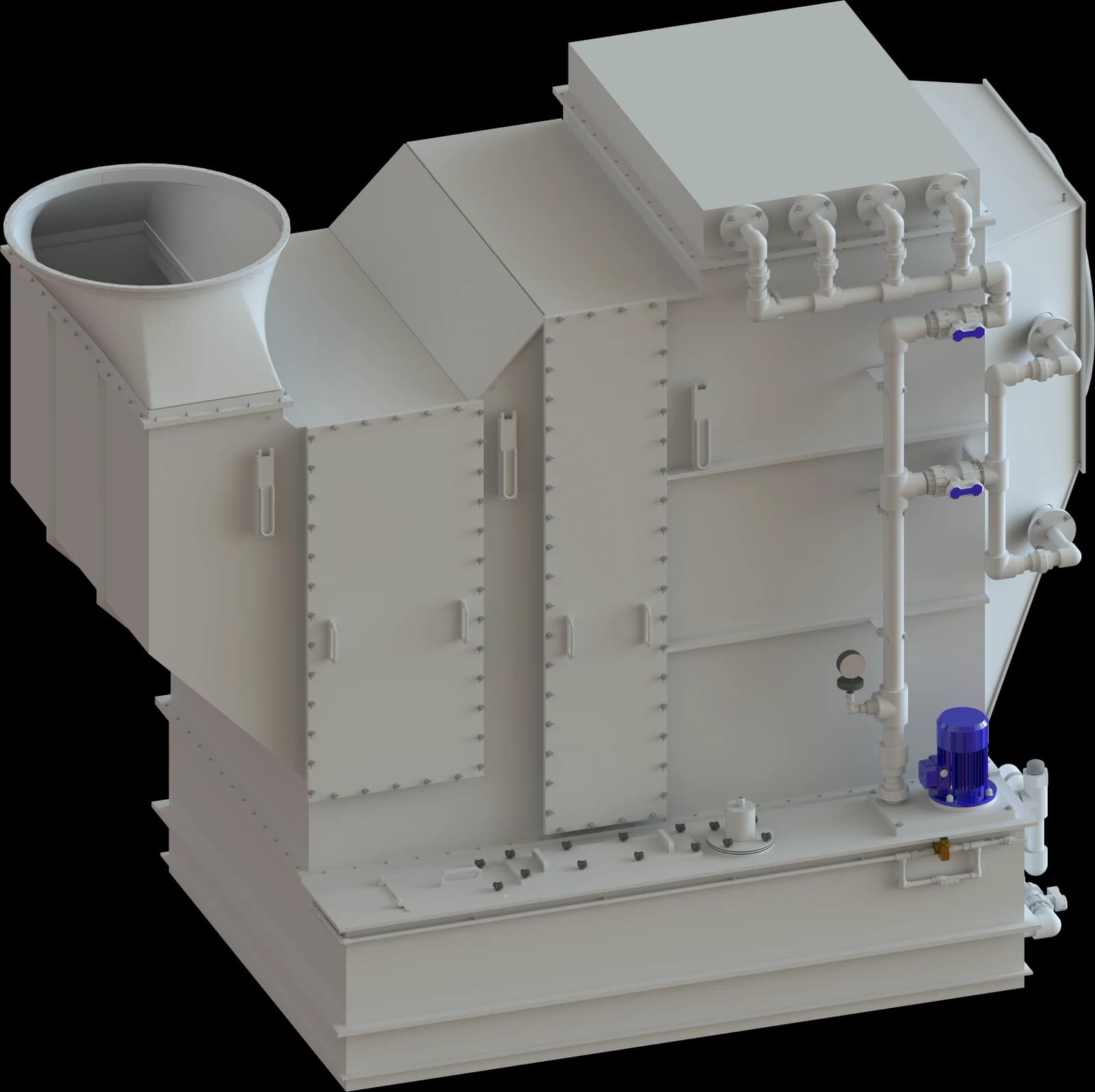
Gas cleaning options
Fibre-bed mist filter
A vertical cylindrical unit with a fibrous filter media packing.
Wet scrubber
Wet cleaning: the contaminated gas contacts an irrigating liquid - water, alkaline or acid solution - neutralising and absorbing the harmful compounds.
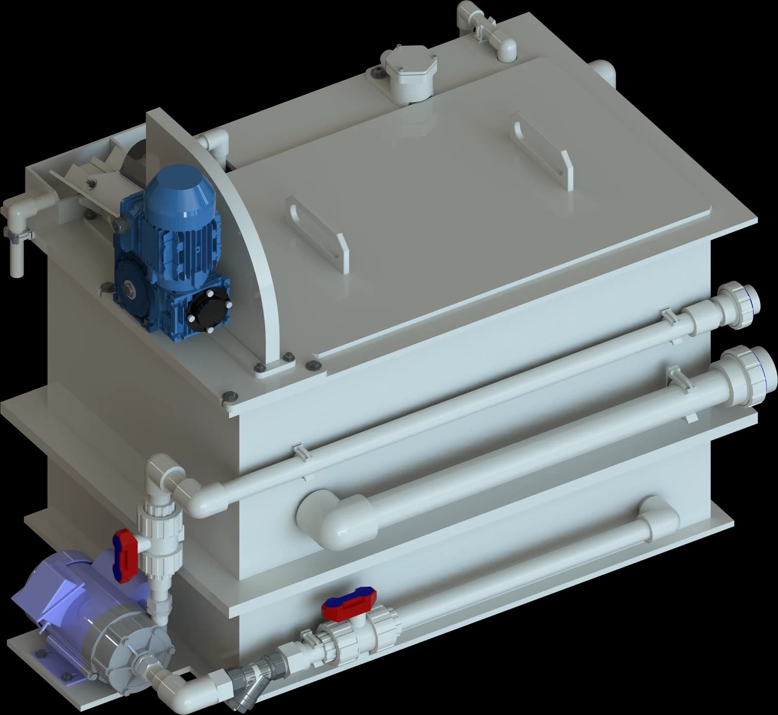
Oil separators
Oil separators on the degreasing tanks keep the process solution free of oil contamination.
How it works: electrolyte carrying the oil film is drawn from the bath surface through an inlet pipe into the first compartment of the vessel, where a disc skimmer continuously lifts the oil off and passes it to a collection vessel. Cleaned electrolyte flows across the baffles into the second compartment and is returned to the tank by a chemically resistant pump.
Level sensors control the pump; an overflow weir guards against spillage and a top-up system protects the pump from dry running. The design delivers effective electrolyte cleaning with minimal solution loss.
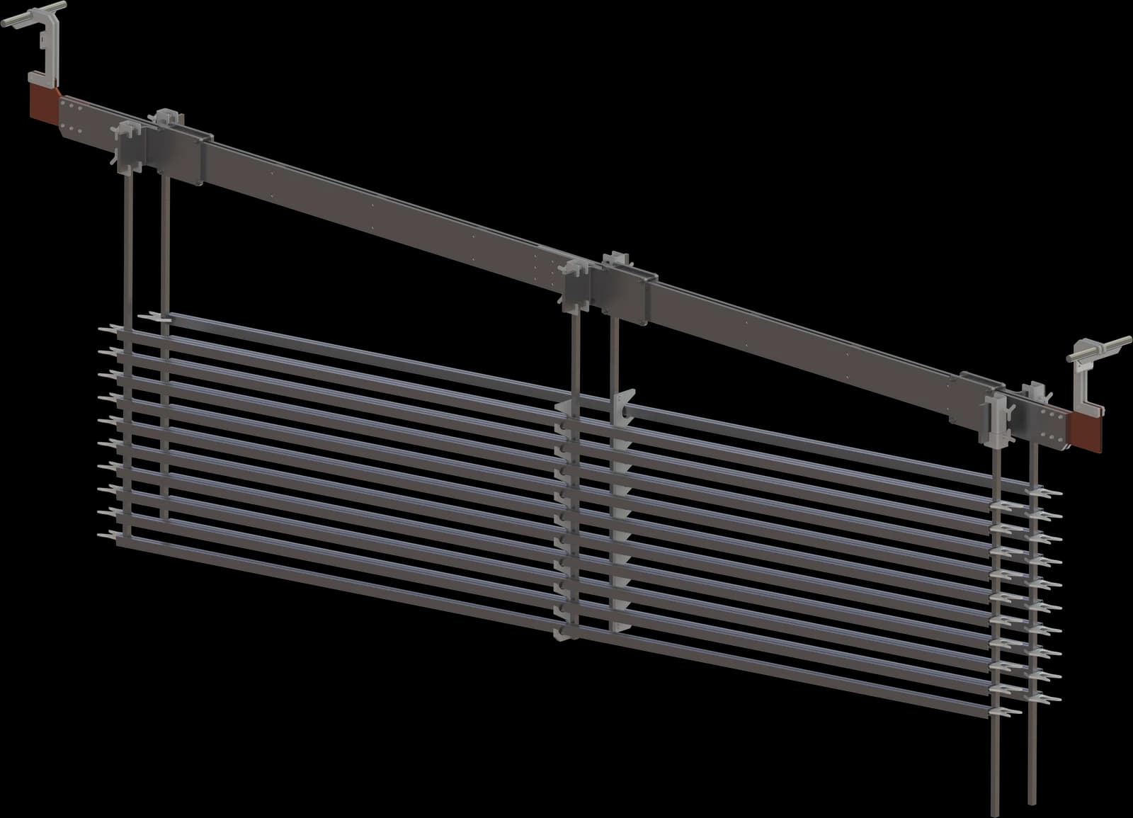
Workpiece carriers
The carrier is a purpose-built transport fixture: it holds the load securely, transfers current, and gives an orderly path for parts or jigs to move between tanks on both automated and manual lines.
On automated plating lines, carriers are not an accessory - they are part of the machine.
Load/unload station
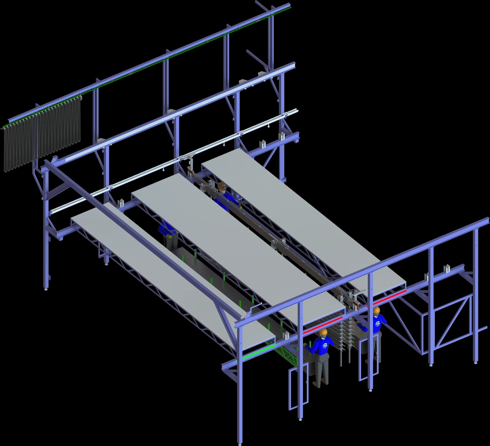
The load/unload station is a reinforced steel structure for mechanised loading and unloading on automated lines. The base is a welded structural steel frame with an anti-corrosion coating rated for the plating-shop environment.
The station carries several loading positions for jigged parts: a multi-position layout serves several process positions at once and lifts the throughput of the whole line.
The space between stations is covered by protective polypropylene roofing, shielding the operator from electrolyte splash and adding a second safety barrier.
Every station is fitted with barrier sensors and LED indication around the perimeter of the working zone. A dwell-time monitor watches how long parts sit at a position and triggers an audible and visual alarm if the line's rhythm is broken.
Rectifiers
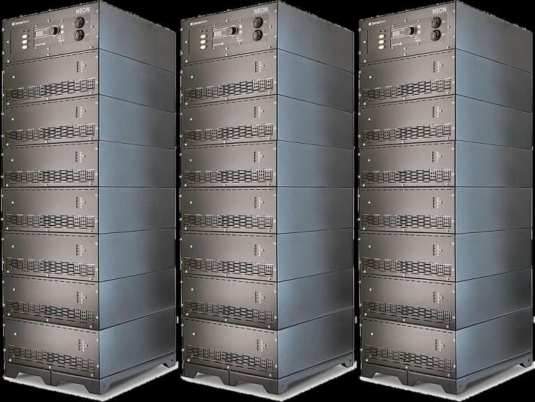
The rectifier converts incoming AC mains into the stabilised, controllable DC that feeds the process tanks and electrochemical machining stations, under heavy industrial duty.
The units are built on inverter (switch-mode) technology with a high-frequency resonant converter: up to 90% efficiency, minimal footprint and weight, and output current ripple no greater than 2%.
A modular architecture makes them serviceable: if one module fails the others keep running, so the line does not stop.
Key advantages
Energy efficiency
Around 90% efficiency - a substantial cut in electricity cost.
Coating quality
Minimal current ripple gives even layer thickness and saves chemistry.
Control accuracy
Holds the process precisely, including work with precious metals.
Intelligent control
Processor control, programmable regimes, integration into the plant control system.
Corrosion resistance
IP54/IP65 enclosures and conformal-coated boards for long life in aggressive environments.
The process route
Five principal stages. Every tank is described in full under the process sequence.
Mechanical preparation
Sets the geometry and surface finish before any film forms: once a part is anodized, the coating cannot be removed without destroying it.
Chemical pre-treatment
Degreasing and etching. Aluminium oxidises instantly in air and absorbs oils from machining coolant - every contaminant has to come off.
Anodizing
The core stage: electrochemical oxidation under current in an electrolyte tank.
Colouring
Where a decorative finish is required - applied immediately after the acid rinse, while the pores are still open.
Sealing
The mandatory final stage: open pores act as capillaries, and without sealing they will destroy the coating over time.
Questions and answers
On a manual line the operator moves the jigs between tanks - suitable for small batches. A semi-automatic line mechanises transport but keeps the operator involved in individual steps, which suits medium volumes. A fully automated line runs to a recipe under PLC/SCADA control with a gantry hoist: consistent immersion times, maximum throughput, minimum labour.
Get a line configuration and a budget estimate
Send us your specification or fill in the form - we reply within one business day.